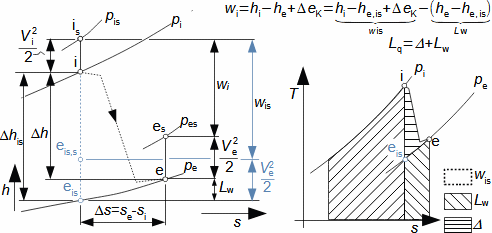
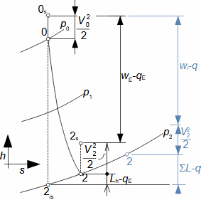
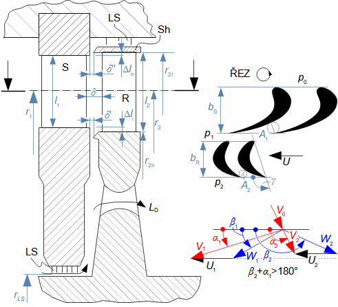
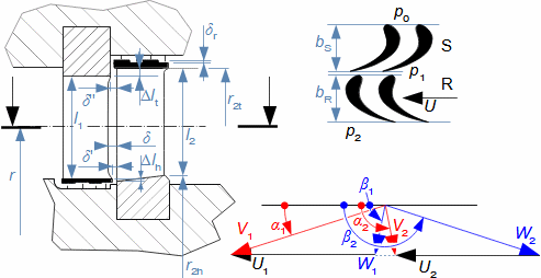
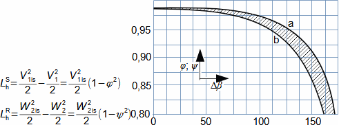
|
– author: –
ŠKORPÍK, Jiří (LinkedIn.com/in/jiri-skorpik)
– issue date: –
March 2024
– title: –
Thermodynamics of heat turbines
– web: –
– provenance: – Brno (Czech Republic)
– email: – skorpik.jiri@email.cz
Copyright©Jiří Škorpík, 2024 |
Expansion in heat turbineGas expansion in turbines smoothly transforms internal thermal, pressure, kinetic, and potential energy into work. Density and temperature change, necessitating knowledge of h-s and T-s diagram design for energy balance calculation. Usually the expansion is associated with high temperature, at least at the inlet, this puts additional special requirements, this time on the blade materials and their cooling. Adiabatic expansionThe adiabatic expansion computational model is used in cases where the turbine is not expected to have a significant heat transfer to the surrounding, even if the temperature of the expanding gas is higher than the surrounding temperature, but they are also well thermally insulated and the expansion is too fast to have a significant heat transfer effect on the expansion.
– 307: – Adiabatic expansion in h-s and T-s charts ![]() |
|
h [J·kg-1] enthalpy; Lq [J·kg-1] loss heat, or sum of different types of energy transformed into internal energy of gas at expansion process; Lw [J·kg-1] internal losses; s [J·kg-1·K-1] entropy; T [K] absolute temperature; wis [J·kg-1] internal work at isentropic expansion (adiabatic expansion with no losses); Δ [J·kg-1] Re-used heat (part of Lq that has been transformed into work in another part of turbine); ΔeK [J·kg-1] difference in kinetic energy between inlet and outlet (usually insignificantly large difference). The index is denotes the isentropic compression states, the index s the stagnation state. The T-s diagram is constructed when the kinetic energy difference is insignificant. The equations are derived in Appendix 307.
– 116: – ![]() Z [-] number of stages; 1+f [1] reheat coefficient (1,02 to 1,04 according to [Kadrnožka, 1991]); ηi [1] internal expansion efficiency between point 1-Z. The index j denotes the j-th stage. The equations are derived for the assumption that all stages process the same enthalpy gradient and the expansion is adiabatic. For clarity, the absolute velocity kinetic energy is not plotted in the figure. The equations are derived in Appendix 116. – Problem 871: –
Calculate the internal power of Steam turbines and the dryness of steam at the end of expansion. The steam flow through the turbine is 33 t·h-1, the internal efficiency of the turbine is 75%, the specific isentropic work of the turbine is 1259.59kJ·kg-1, the pressure at the turbine outlet is 3 kPa, at the turbine inlet are 3.5 MPa at temperature 450 °C. The solution of this problem is shown in Appendix 871.
Polytropic expansionThe computational model of polytropical expansion is used in cases where the expansion is affected by heat transfer with surrounding. This occurs, for example, in radial turbines with large disk area, in cooling of thermally exposed parts of the turbine, etc. |
– 685: – Polytropic expansion for case q>0 ![]() epol state of gas at the machine outlet during reversible polytropic expansion. wpol [J·kg-1] internal work during reversible polytropic expansion (expansion without losses) at same heat transfer with surrounding q - heat q must have the same impact on entropy and temperature as in the actual process. The index pol denotes reversible polytropic expansion. The T-s diagram is constructed when the difference of kinetic energies is insignificant. The procedure for constructing the T-s diagram is described in Appendix 685. – 686: – Polytropic expansion for case q<0 (Cooled expansion) ![]() (a) case when te,is>te; (b) case when te,is=te (apparently isentropic expansion). The T-s diagram is constructed when the effect of the kinetic energy difference is insignificant. Thermodynamic calculation of heat turbine stageFor thermodynamic calculations of the heat turbine stage, findings from previous articles in these proceedings can be utilized (turbomachinery.education). Here, only special knowledge on heat turbine stage thermodynamics is summarized and supplemented: h-s stage charts; usual values of similarity coefficients; heat turbines stages with straight blades; heat turbines stages with twisted blades; conical stages and stages of radial turbines. |
– 908: – ![]() Lh [J·kg-1] profile losses;ΣL [J·kg-1] total losses of stage; V [m·s-1] absolute velocity; qE [J·kg-1] heat transferred in the surroundings of the streamline under investigation.
|
– 350: – ![]() Sh-shroud; LS-labyrinth seal. A [m2] flow area of blade passage; b [m] width of blade row; l [m] length; LD [kg·s-1] discharge of working fluid from gap between discs (it is loss); r [m] radii of blades (index t denotes tip of blades, index h denotes root of blades); U [m·s-1] blade speed; W [m·s-1] relative velocity; α [°] angle of absolute velocity; β [°] angle of relative velocity; γ [°] stagger angle; δ [m] sizes of axial gaps. |
– 353: – ![]() The blade roots are not drawn in the pictures.
– 178: – Values of velocity coefficients of steam turbine blade cascades ![]() a-pressure row (reaction 0,5); b-equal pressure row. Δβ [°] angle of camber of flow; φ [1] velocity coefficient in stator passage; ψ [1] velocity coefficient in rotor passage. Index 1 indicates parameters upstream of the rotor blade row, index 2 indicates parameters downstream of the rotor blade row, index S indicates the stator blade row, index R indicates the rotor blade row. Data source [Krbek, 1990, p. 82]. |
|
– Problem 188: –
Design the straight blade lengths, velocity triangles and calculate the axial force acting on the rotor of the reaction stage of steam turbines. The steam flow rate through the stage is 12 kg·s-1, rotational speed is 50 s-1, steam pressure at the stator inlet is 1,25 MPa at temperature 320 °C, mean diameter of the blade length is 650 mm, reaction is 0,5, the absolute velocity angle at the stator outlet is 20°, the stator and rotor velocity coefficient is the same 0,93. The isoentropic drop of the stage shall be 21,3 kJ·kg-1. Compare the pressure coefficient with the pressure coefficient for an ideal reaction stage. The problem is taken from [Krbek, 1990 p. 110]. The solution of this problem is shown in Appendix 188.
![]()
A special case of the impulse stage is the Curtis stage. In this case, the available energy is transformed into kinetic energy in the stator row of blades, but then flows through more than one row of rotor blades, between which another equal pressure stator blade is inserted, which only changes the direction of flow, see Figure 913, p. 13.10. In the case of very small steam turbines, a reversal passage can also be used whereby the steam passes through the rotor blade row twice, see Figure 914, p. 13.10. |
|
– 913: – ![]() Velocity triangle of Curtis stage in this figure is for the case of ideal flow without profile losses. wC [kJ·kg-1] Euler work of ideal Curtis stage; wR=0 [kJ·kg-1] Euler work of ideal impulse stage. The derivation of the ideal Curtis stage Euler work equation is shown in Appendix 913. – 914: – ![]() Single stage steam turbine for low flow and high enthalpy drop: The turbine is designed as the Curtis stage. The turbine contains only one Laval nozzle. Instead of a second stator row, there is a reversal passage that brings the steam back to the first rotor row. Figure from [Miller et al. 1972, p. 188].
|
– 351: – ![]() ε [°] blade cutting at tip and root of blades.
– 547: – ![]() |
– 393: – Radial single stage steam turbine ![]()
Blade cooling performance and methods to increase blade temperature stabilityThe high temperature of the working gas also allows for high thermal efficiency of the cycle in which the turbine operates. However, this places high demands on the blade material and surface treatment. Another possibility is blade cooling. |
– 1001: – Necessary ingredients of steel according operating temperature ![]() t [°C] operating temperature of blades. According to data from [Anon., 2014].
– 782: – Steam turbines blade made of steel and titanium alloy ![]() Doosan Škoda Power 1375 mm steam turbines last stage blade.
Surface treatments such as polishing can in turn increase corrosion resistance. Especially at high temperatures in the presence of oxygen, there is a risk of increased scale formation (formation of hard oxides - rust). |
– 682: – ![]() GE MS5002 series combustion turbine blades with cooling passages [Anon., 2011]
|
ReferencesŠKORPÍK, Jiří, 2023, Flow of gases and steam through nozzles, fluid-dynamics.education, Brno, [online], ISSN 1804-8293, https://fluid-dynamics.education/flow-of-gases-and-steam-through-nozzles.html.
ŠKORPÍK, Jiří, 2024, Technická termomechanika, engineering-sciences.education, Brno, ISSN 1804-8293, https://engineering-sciences.education/technicka-termomechanika.html.
ŠKORPÍK, Jiří, 2025, Meze použití materiálů, engineering-sciences.education, Brno, https://engineering-sciences.education/meze-pouziti-materialu.html.
ANON., 2011, MS 5002 Gas Turbine a Through D Evolution, ge.com.
ANON., 2014, Co nám může v budoucnosti nejvíc chybět? Na čem jsem závislí, Technický týdeník, 01/2014, Business Media CZ, Praha, ISSN 0040-1064.
BENEŠ, Antonín, DRASTÍK, František, HOSTINSKÝ, Zdeněk, KOUTSKÝ, Jaroslav, NĚMEC, Josef, 1974, Nauka o kovech, SNTL, Praha.
DIXON, S., HALL, C., 2010, Fluid Mechanics and Thermodynamics of Turbomachinery, Elsevier, Oxford, ISBN 978-1-85617-793-1.
DOKOUPIL, Eduard, 2015, Turbíny pro Luftwaffe: zrod a popis prvních německých proudových motorů, Dokoupil Eduard, Světlá, ISBN 978-80-260-8153-1.
HOCKO, Marián, 2012, Transformace leteckých lopatkových motorů na spalovací turbíny, Západočeská univerzita v Plzni, Plzeň, ISBN 978-80-261-0218-2.
KADRNOŽKA, Jaroslav, 1991, Teorie lopatkových strojů, Vysoké učení technické v Brně, Brno, ISBN 80-214-0275-X.
KADRNOŽKA, Jaroslav, 2004, Tepelné turbíny a turbokompresory, Akademické nakladatelství CERM, s.r.o., Brno, ISBN 80-7204-346-3.
KOUTSKÝ, Jaroslav, 2005, Development and application of Original Special Steels-Base of World Famous Level of Skoda-Works Steam turbines, Energetické stroje-termomechanika-mechanika tekutin , Fakulta strojní Západočeské university v Plzni, Plzeň.
KRBEK, Jaroslav, 1990, Tepelné turbíny a turbokompresory, Vysoké učení technické v Brně, Brno, ISBN 80-214-0236-9.
MILLER, Rudolf, HOCHRAINER, A., LÖHNER, K., PETERMANN, H., 1972, Energietechnik und Kraftmaschinen, Rowohlt taschenbuch verlag GmbH, Hamburg, ISBN 3-499-19042-7.
MÍŠEK, Tomáš, 2014, Vývoj ultra dlouhé lopatky Doosan Škoda Power pro kondenzační Steam turbines, Technický týdeník, 10/2014, Business Media CZ, Praha, ISSN 0040-1064.
POLSTER, Burkard, 2014, Q.E.D. Krása matematického důkazu, Dokořán s.r.o., Praha, ISBN 978-80-7363-532-9.
ŠKOPEK, Jan, 2007, Parní turbína-tepelný a pevnostní výpočet, Západočeská univerzita v Plzni, Plzeň, ISBN 978-80-7043-256-3.
SMITH, F., 1965, A simple correlation of turbine efficiency, Journal of the Royal Aeronautical Society, 69, 467–470.
– Online shop –
If you found this article helpful, you can purchase the full version in my online shop. Thank you for your support, and I wish you every success with your projects.
Jiří Škorpík author ©Jiří Škorpík, LICENCE
|