3.

SHAPES OF BLADES AND FLOW PARTS OF TURBOMACHINES

3.3 . . . . . . . . . . . . . .
3.3 . . . . . . . . . . . . . .
3.6 . . . . . . . . . . . . . .
3.8 . . . . . . . . . . . . . .
3.9 . . . . . . . . . . . . . .
3.12 . . . . . . . . . . . . . .
3.14 . . . . . . . . . . . . . .
3.15 . . . . . . . . . . . . . .
3.16 - 3.20 . . . . . . . . . .
3.2
author:
ŠKORPÍK, Jiří – LinkedIn.com/in/jiri-skorpik
issue date:           
September 2022; November 2023 (2nd ed.)
title:
Shapes of blades and flow parts of turbomachines
proceedings:
provenance:
Brno (Czech Republic)
email:
skorpik.jiri@email.cz

Copyright©Jiří Škorpík, 2022-2023
All rights reserved.

KeywordsChapter: Types of profile cascades
3.3

Types of profile cascades

Stagger angle

Confuser cascade

Pressureless cascade

Diffuser cascade

The type of a profile cascades is determined by the stagger angle (inclination in the cascade). The size of the inlet and outlet flow area of a cascade is essential for the resulting velocities of the working fluid when flowing through the profile cascade. Any basic type of profile cascades with the same pitch can be constructed from the same profile by simply turning the profile or changing the stagger angle of the profile in the cascade, see Figure 1:

Relationships between basic types of profile cascades
1: Relationships between basic types of profile cascades
(a) confuser cascade - also called overpressure, turbine cascades; (b) pressureless cascade - with same flow area pressure and velocity between inlet and outlet do not change; (c) diffuser cascade - also called overpressure, compressor or turbine cascades in case A1 is critical flow area. A [m2] flow area. γ [°] stagger angle of profile in cascade; s [m] pitch. The profiles are simplistically drawn as if they were made of sheet.

Blade profile

The profile of the blade means its outline on a particular section. This chapter describes the methods for creating the blade profile drawing and the rules for determining the shape of the blade profile.

Profile drawing

Profile coordinates

Camber line

Chord

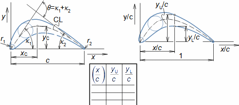
The blade profile can be recorded using blade profile geometry rules. The choice of the method of recording the blade profile shape depends on the medium of this recording, or the most suitable method in relation to the required form of production documentation. Currently, graphical output (using vector graphics) is sufficient, e.g. in CAD systems, as machine tools and computing software are able to work directly with such output, but other forms of blade profile notation exist. For example, they are written in tabular form in the x; y coordinates and using the shape of the camber line of the profile, see Figure 2.

KeywordsChapter: Blade profile
3.4
Blade profile plotted using coordinates
2: Blade profile plotted using coordinates
CL-camber line of profile (geometric location of centres of circles inscribed in profile). θ=κ1+κ2 [°] camber; yC [m] maximum camber; xC [m] position of maximum camber; κ1, κ2 [°] angles of camber line (at leading edge of profile and trailing edge of profile); c [m] chord; r [m] radius.

Camber line

Pressureless cascade

The shape of the camber line of the profile is most often formed by parts of a circle, parabola, logarithmic curve and other types of curves (or two curves with a common tangent at the point of common contact). Typical values of the xC/c ratio are between 0,4 and 0,5, with pressureless cascades the ratio tends to be around 0,5.

Profile shape

Droplet shape

The profile shape is based on the requirements that the blade must meet in the machine, usually the profile resembles a curved drop. The droplet shape allows the ideal adhesion of the fluid to the blade surface and therefore follows the camber of the blade.

Coanda effect

Henri Coandă

Flow separation

The property of a fluid to follow a surface is called the Coanda effect, after the Romanian engineer Henri Coandă (1886-1972), who studied the wrapping of surfaces and bodies. The Coanda effect is clearly visible when water is drawn from a cup that does not have a rim around the neck. Up to a certain angle of inclination of the cup, the water runs down the outer surface of the cup instead of flowing directly to the ground. The pressure of the water stream on the surface of the cup is caused by the viscosity, buoyancy, and lower pressure in the flowing liquid than the ambient air pressure. A similar phenomenon occurs when water flows around a cross pipe, for example in a condenser, etc. The adhesion of the fluid to the wrapping surface has limits, beyond which the flow separation from the wrapping surface, these limits are dealt with in the aerodynamics of profile cascades.

KeywordsChapter: Blade profile
3.5

Airfoils

Abbott and Doenhoff, 1959

A suitable profile can be selected from profile catalogues based on aerodynamic requirements. The shapes and aerodynamic data of thin and low camber profiles can be obtained from extensive airfoil catalogues used in aeronautics, for example [Abbott and Doenhoff, 1959]. If a suitable blade profile is missing from the catalog, it must be developed and experimentally verified.

Base airfoil

The development of a new profile is usually based on different camber of the so-called base airfoil, which is a symmetrical smooth airfoil, see Figure 3. There are many base airfoils differing from each other in shape, aerodynamic characteristics and other properties, see for example [Abbott and Doenhoff, 1959]. The development of a new profile resulting from the cambering of a base airfoil makes it possible to systematically define the aerodynamic differences between different camber and to clearly catalogue these new profiles according to the base airfoil they are based on.

Profile resulting from camber of basic airfoil
3: Profile resulting from camber of basic airfoil

Strength

Profile cross-section

Camber line

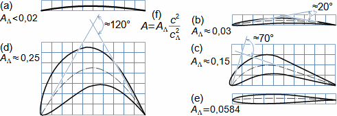
In addition to aerodynamic requirements, the airfoil must also meet strength requirements, which affect the required profile thickness at the root of the blades, where the stresses from centrifugal forces and bending are highest. Figure 4 shows typical blade root profiles and their cross-section.

Profile cross-sections at root of blades
4: Profile cross-sections at root of blades
(a) profile common in radial stages or axial stages with very little camber; (b) thin profile with little camber of flow common in hydraulic machines or turbocompressors (camber line is circle); (c) profile of lightly loaded heat turbine blades (camber line is circle and straight line); (d) profile of heavily loaded heat turbine blade (camber line is parabola); (e) profile of wind turbine blade (NACA 63-209); (f) Cavalieri formula for recalculating profile cross-section for different chord lengths. A [mm2] actual blade profile cross-section; AΛ [mm2] blade profile cross-section at cΛ chord length (numbers for profiles in this figure are for 1 mm chord length, the so-called specific profile cross-section).
KeywordsChapter: Blade profile
3.6

Noise

Contaminants

A frequent requirement for blade profile characteristics is low noise (fans, wind turbines, etc.), which is mainly influenced by the radii of the leading and trailing edges. Wind turbine blade profiles are also subject to requirements for the least possible deposition of contaminants (dust) on the surface, which is a function of the shape, roughness and material of the surface. In addition, for hydraulic machines, the profiles are more or less sensitive to cavitation, etc.

Geometry and aerodynamic quantities of blade cascades

The geometry of the blades, or their shape and especially their camber must meet the requirements for the camber of flow in the blade passage resulting from the shape of the velocity triangles. The amount of camber of flow in the blade cascade is also a function of the blade pitch or the density of the profile cascade.

Camber

Camber of flow

Angle of attack

Angle of deviation

Mean aerodynamic velocity

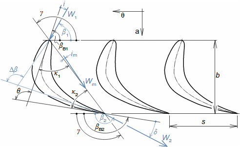
The camber of a blade and a camber of the flow with a properly designed blade profile has approximately the same value. For this, it is necessary that the required velocity at the inlet to the blade cascade must maintain some angle of attack with the camber line, because at the outlet of the profile cascade the direction of relative velocity deviates from the camber line by a deviation angle, Figure 5.

Basic geometric and aerodynamic angles of profile cascade
5: Basic geometric and aerodynamic angles of profile cascade
βB1, βB2 [°] inlet and outlet angle of blade profile; i [°] angle of attack; δ [°] angle of deviation; Δβ [°] camber of flow; b [m] width of profile cascade; W1, W2 [m·s-1] attack and outflow velocity; Wm [m·s-1] mean aerodynamic velocity in cascade; im [°] angle of attack of mean aerodynamic velocity.
KeywordsChapter: Geometry and aerodynamic quantities of blade cascades
3.7

Density of profile cascade

Number of blades

The required camber of flow is a function of the camber, of pitch, of chord respectively the number of blades, where the ratio between the length of the chord and the pitch of the profile cascade is referred to as a density of profile cascade, see Formula 6.

Density of profile cascade
6: Density of profile cascade
σ [1] density of profile cascade.

Diffuser cascades

Confuser cascades

Mean width of blade passage

Pfleiderer, 2005

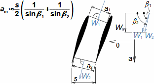
With a higher density of the profile cascade, a greater camber of flow can be expected and vice versa. On the other hand, the number of blades and frictional losses in the cascade increase with the density of the profile cascade. Thus, there is an optimum value for the density of the profile cascade. In the case of diffuser profile cascades, the optimum density should be sought to be one at which the c/am ratio is around 2,5, where am is the mean width of blade passage [Pfleiderer and Petermann, 2005, p. 408], see Formula 7. These ratios are valid for profile cascades composed of thin, low camber profiles.

Estimation of optimal density of profile cascade
7: Estimation of optimal density of profile cascade
am [m] mean width of blade passage. The derivation of the equation is shown in Appendix 5.

Zweifel coefficient

Japikse, 1997

The density of profile cascade with highly camber heat turbine profiles can be approximated by the Zweifel coefficient. The Zweifel coefficient CL,θ is the ratio of the tangential component of the force on the blade from the fluid flow Fθ to the product of the blade area and the dynamic pressure of the relative velocity at the outlet of the blade cascade, see Formula 8. The value of this coefficient for the designed profile cascade should be in the range of 0,75...0,85 for modern profiles with high blade material strength up to 1 [Japikse, 1997, p. 6-17].

KeywordsChapter: Geometry and aerodynamic quantities of blade cascades
3.8
Zweifel coefficient
8: Zweifel coefficient
CL [1] Zweifel coefficient; Fθ [N] tangential component of force on blade acting by flow; l [m] blade height; ρ [kg·m-3] density of working fluid. The derivation of the equation is shown in Appendix 6.

Width of profile cascade

The width of the profile cascade b, defined in Figure 5, is based on the required length of the chord, which is a compromise between the optimal aerodynamic design and the required strength of the blades and their roots. If we know the width, it is not a problem to determine the number of blades respectively the pitch from the density of profile cascade σ.

Range of values of some geometric and aerodynamic variables of blade cascades

When designing the most suitable blade parameters, it is crucial whether the stage is axial or radial. The design of the camber θ is influenced by whether it is a turbine stage or a working machine stage. Furthermore, the goal is usually to achieve the smallest possible values of the difference between the inlet and outlet velocity respectively the lowest possible loss of outlet velocity.

Axial stage

Turbines

Velocity angle

When designing the geometric and aerodynamic parameters of axial turbine stages, the goal is to achieve a small output velocity V2 and the largest possible value of the tangential component of the input velocity V, respectively the smallest possible angle of the absolute input velocity α1 (for manufacturing reasons, the minimum value of this angle is usually around 8°, depending on the possibility of production and the strength of the blades). The advantage of a smaller angle α1 is also that for the required velocity component V, a smaller velocity V1 is sufficient, thus reducing frictional losses in the stator cascade of blades.

Working machines

Camber line

Flow separation

Diffuser profile cascades are most commonly used for the working machine stages. Diffuser profile cascades are more sensitive to flow separation from the blade as the camber increases and therefore a small camber of flow Δβ is required, ranging from 15° to 30°. The largest values of Euler work can be achieved for the case V=0.

KeywordsChapter: Range of values of some geometric and aerodynamic variables of blade cascades
3.9

Radial stage

Angles of camber line

Francis turbine

The properties of the radial stages depend significantly on the angle of the camber line of the profile on the rotor circumference (Figure 9), see dimensionless characteristics of radial stages. However, the best aerodynamic properties have backward curved blades whose camber line corresponds to a logarithmic spiral, see Problem 1. In the case of turbine radial stages, the angle of the camber line of the profile at the rotor circumference other than 90° is practically only found in Francis turbines.

Effect of camber line angle of profile on blade shape of radial stages of working machines
9: Effect of camber line angle of profile on blade shape of radial stages of working machines
(a) backward curved blades; (b) radial blades; (c) forward curved blades.

Shapes of blades

The shape of the blade can be either straight, i.e. it is a blade with the same profile along its length, or twisted, where the shape of the profile and the stagger angle of the profile changes along the length of the blade. Apart from these two basic shapes, we can also talk about the blade shapes of radial stages.

Straight blades

Straight blades of axial stages are usually used where a small ratio between blade length and mean blade radius can be achieved, so that the spatial character of the flow is not so apparent. The advantage of straight blades is the simplicity of design, manufacture and cost. They are often manufactured by drawing as circular wires, see Figure 10.

KeywordsChapter: Shapes of blades
3.10
Examples of straight blades
10: Examples of straight blades
left-static steam turbine blade made of drawn profile with machined groove for attachment at the base of the blade; right-rotor steam turbine blade made of drawn profile with machined tip and foot made of forging.

Twisted blades

Stagger angle

Twisted blades of axial stages are blades with a change of stagger angle of profile in the cascade along the length of the blade and usually with a change of profile. The design of the twisted blade takes into account the spatial character of the flow in the stage and the changes in the velocity triangle and reaction, respectively (see 2D calculation of the reaction of a Kaplan turbine). The resulting blade shape is complex and increases manufacturing costs compared to shaped straight blades (usually produced on a 5-axis milling machine from a shaped casting, but there are other manufacturing technologies for hollow blades).

Untwisting of blades

Integral snubber

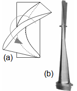
Strongly twisted and long rotor blades are subject to untwist by centrifugal forces (Figure 11a), other deformations are from the working fluid flow. This is solved by an integrated blade vibration snubber, which only clicks into the vibration snubber of the neighbouring blade at certain machine rotational speeds to stiffen the blade cascade and stop further blade untwisting, see Figure 11b. It is therefore necessary to take into account that the profile geometry will be different at machine standstill than at nominal rotational speed. Untwisting is also evident in wind turbine blades, which also change shape due to axial force from the airflow.

KeywordsChapter: Shapes of blades
3.11
Untwisting of twisted blade
11: Untwisting of twisted blade
(a) illustration of direction of twisting of twisted blade by centrifugal forces; (b) twisted blade with integrated vibration snubber.

Radial blades

Shroud disc

The blades of radial stages are either of such shape that they form purely radial blade passages, or such that they extend into the axial direction (Figure 12(b, c)). In the case of purely radial blades, they are usually straight blades of often constant width, sometimes made of sheet metal (see Problem 3).

Examples of radial blade designs for working machines
12: Examples of radial blade designs for working machines
(a) purely radial blades; (b), (c) radial-axial blades (in case of (c) blades are equipped with shroud disc to reduce internal leakage). The index t indicates the tip of the blade, h the root of the blade or the radius of the shaft. rm [m] mean radius of blade; ε [°] inclination of streamline with respect to axis of rotation.

Inducer

Cavitation

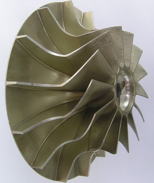
The axial part of radial blades is used in turbine stages and working machines. In turbines, it has the function of uniformly transferring flow from radial to axial direction with a reduction of tangential velocity component V. The axial part is called the inducer in the case of working machine stages. In pumps, the inducer is usually not pronounced (Figure 12c) to avoid large differences between velocities at the root and tip of the inducer blades, which could cause cavitation. The axial part of the radial rotor is calculated at three radii, i.e., in addition to the middle one, at the tip and at the root of the blade, so that the angle of attack for working machines or the angle of deviation for turbines is constant over the height of the blade (see 2D-calculation of inducer). The manufacture of this part of the blade by machining is difficult and therefore this type of rotor consists of several parts - see Figure 13.

KeywordsChapter: Shapes of blades
3.12
Example of radial rotor turbocompressor
13: Example of radial rotor turbocompressor
The rotor of the radial compressor is glued together from a casting (rotor is made of cast aluminium alloy) and a precision forging made of duralumin (higher loads require higher quality duralumin alloy, which cannot be cast), the rotor diameter is 160 mm, anodized finish.

Bladeless stator

Bladeless diffuser

Bladeless confuser

Rotatable blades

Radial stages very often contain a bladeless stator. Although the bladeless diffusers have lower efficiency at nominal parameters, they have a smoother efficiency curve when the flow rate changes than a stage with a blade diffuser. Good flow change characteristics can also be achieved with blade diffusers, but at the cost of rotatable blades, which are more technologically demanding and expensive, including the control mechanism. For the same reasons, so-called bladeless diffusers are used for radial turbine stages, or the stator blades are rotatable, as for example in some turbine rotors of turbochargers. A combination of stator blades and a more higher radial gap between the blades and the rotor is also possible, which acts as the bladeless diffuser (Figure 12b), or in turbines a bladeless confuser.

Shapes of turbomachine branches

The shape of the branch is based on the purpose, the type of machine and especially the direction of the working fluid flow from or to the blade section. If the blade section connects to the branch radially or diagonally, then the branch is of spiral design. If the blade section connects to the branch axially, then axial branches are used. In both cases, the shape and size of the branch should be such that the circumference of the connecting blade cascade is at the same pressure. There are no significant density changes in the branches because they are fluid transport passages.

KeywordsChapter: Shapes of turbomachine branches
3.13

Spiral casings

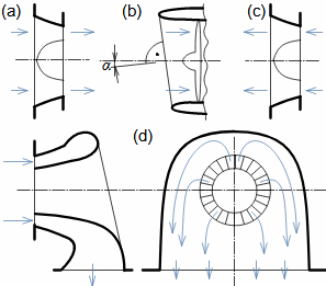
The basic design of the spiral casing is based on the theory of potential flow, in which the streamlines have the shape of logarithmic spiral. The basic spiral casings shapes are shown in Figure 14, with some shapes not satisfying the conditions of the potential flow equations, resulting in vortices. However, they have other advantages - in particular, they reduce the required diameter of the spiral casing, which results in a much larger diameter than the rotor diameter for a constant casing width and potential flow. Spiral casings can also be reduced by ending them at less than 360°, see Problem 4 - shortened casings can be used where size is a more important parameter than efficiency.

Basic spiral casings
14: Basic spiral casings
(a) rectangular (constant casing width - mainly used in fans); (b) trapezoidal (gradual extension leads to lower losses than step extension and its shape is very close to the condition for potential flow); (c) circular; (d) tangential outlet casing. b [m] casing width.

Axial branches

Side branches

Jet engine

Mattingly et al., 2002

Figure 15 shows some designs of axial and side branches. In the case of Figure 15b, the jet engine axial beveled branch that allows for more optimal pressure distribution of the first stage of compressor. The maximum engine power (air consumption) is during takeoff, and therefore the angle α approximately corresponds to the pitch angle during takeoff. More details on this issue, including the calculation of the optimal deflection angle α, are given in [Mattingly et al., 2002, p. 424].

Branches of axial stages
15: Branches of axial stages
(a) axial inlet (e.g. combustion turbine inlet); (b) jet engine inlet; (c) axial outlet (e.g. axial fan outlet); (d) side branches (e.g. axial compressor side branches). α [°] deflection angle.
KeywordsChapter: Problems
3.14

Problems

Problem 1:
Find the optimum shape of the camber line of the radial fan blade profile with backward curved blades. The given parameters are: r1=15,25 mm, r2=30 mm, β1=120°. The solution of this problem is shown in Appendix 1.
Shape of camber line of profile with backward curved blades
(a) cross-section of rotor and marking shape of relative velocity streamline; (b) quotation of logarithmic spiral; (c) relation between angles of relative velocity in potential flow through rotor with constant height of blades. ψ-relative velocity streamline. l [m] height of blades; V [m·s-1] absolute velocity; U [m·s-1] tangential velocity; W [m·s-1] relative velocity; β [°] angle of relative velocity; φ [°] angle of logarithmic spiral for its investigated point distant from centre of spiral by r.
§1   entry:   r1; r2; β1 §3   calculation:   φ2
§2   proof:   CL is logarithmic spiral §4   calculation:   r for selected φ
Symbol descriptions are in Appendix. 1.
Problem 2:
The figure shows a impeller of a respiratory radial fan with backward curved blades printed on a 3D printer. Users of this fan complain about noise. Make suggestions to change the geometry of the blades, which should lead to a reduction in fan noise. The solution of this problem is shown in Appendix 2.
Defectively designed fan with backward curved blades
T-tangent to the camber line of the profile, which in this case is a circular arc.
Problem 3:
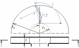
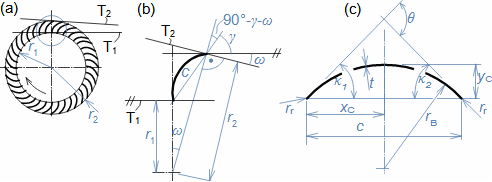
Design the blade geometry and stagger angle of a low pressure radial fan with forward curved blades. The rotor dimensions are: r1=24,6 mm, r2=28,9 mm, β1=158,9°, β2=18,8°. The blade is a single thin sheet. The camber line is formed by a circular arc. The design is made for an angle of attack and an angle of deviation of 3°. The solution of this problem is shown in Appendix 3.
KeywordsChapter: Problems
3.15
Low pressure fan blade with forward curved blades
(a) rotor; (b) stagger angle detail; (c) manufacturing drawing of blade. ω [°] auxiliary angle.
§1   entry:   r1; r2; β1; β2; i; δ §4   derivation:   equations for c; ω; γ
§2   figure:   relationship between geometric and aerodynamic quantities §5   calculation:   ω; γ; c; κ1, 2
§3   calculation:   βB1; βB2 §6   calculation:   rB; yC; xC
Symbol descriptions are in Appendix 3.
Problem 4:
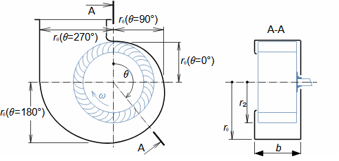
The figure shows a drawing of a spiral casing of a radial fan with forward curved blades, propose the dimensions of this spiral casing. The casing has a rectangular cross-section. The outer radius of the impeller is 28,9 mm, the width of the casing is 23,1 mm, the tangential component of the absolute velocity at the outlet of the impeller is 20,9 m·s-1 and the airflow is 100 m3·h-1. The calculation is carried out for the potential flow case. The solution of this problem is shown in Appendix 4.
Schéma nízkotlakého ventilátoru
§1   entry:   r2; b; V; Q §2   calculation:   rθ for selection θ
Symbol descriptions are in Appendix 4.

References

ABBOTT, Ira, DOENHOFF, Albert, 1959, Theory of wing sections, including a summary of airfoil data, Dover publications, inc., New York, ISBN-10:0-486-60586-8.
JAPIKSE, David, 1997, Introduction to turbomachinery, Oxford University Press, Oxford, ISBN 0–933283-10-5.
MATTINGLY, Jack, HEISER, William, PRATT, David, 2002, Aircraft Engine Design, 2002, American Institute of Aeronautics and Astronautics, Reston, ISBN 1-56347-538-3.
PFLEIDERER, Carl, PETERMANN, Hartwig, 2005, Strömungsmaschinen, Springer Verlag Berlin, Heidelberg, New York, ISBN 3-540-22173-5.
©Jiří Škorpík, LICENCE