4.

AERODYNAMICS OF PROFILE CASCADES

Jiří Škorpík, skorpik.jiri@email.cz
4.3 . . . . . . . . . . . . . .
4.5 . . . . . . . . . . . . . .
4.5 . . . . . . . . . . . . . .
4.8 . . . . . . . . . . . . . .
4.9 . . . . . . . . . . . . . .
4.10 . . . . . . . . . . . . . .
4.11 . . . . . . . . . . . . . .
4.13 . . . . . . . . . . . . . .
4.14 . . . . . . . . . . . . . .
4.2
author:
ŠKORPÍK, Jiří, ORCID: 0000-0002-3034-1696
issue date:           
September 2022
title:
Aerodynamics of profile cascades
proceedings:
provenance:
Brno (Czech Republic)
email:
skorpik.jiri@email.cz

Copyright©Jiří Škorpík, 2022
All rights reserved.

 AERODYNAMICS OF PROFILE CASCADES
4.3

Basic concepts of aerodynamics of profile cascades

Airfoil aerodynamics

Drag

Lift

The aerodynamics of profile cascades is based on the definitions of aerodynamic quantities used in the description of the airfoils aerodynamics [Škorpík, 2022]. This means that for a profile included in a profile cascade, one can also distinguish between drag and lift, which can be calculated using the same formulas as in the case of airfoils, with the difference that instead of the attack velocity, the mean aerodynamic velocity in the cascade is assumed, so that the drag is in the direction of this mean velocity and the lift is perpendicular to this velocity, see Equation 1.

Formulas for blade drag and lift in blade cascade
1: Formulas for blade drag and lift in blade cascade
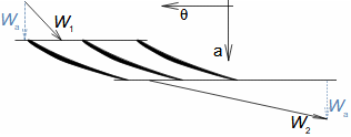
(b) section through linear blade cascade; (b) formulas for calculating drag and lift of straight blade in linear blade cascade; (c) relations between velocities and forces acting on straight blade. D [N] drag; L [N] lift; F [N] force on blade; ρ [kg·m-3] working fluid density; Wm [m·s-1] mean aerodynamic velocity in cascade; c [m] chord; γ [°] stagger angle of profile in cascade; b [m] width of blade cascade; l [m] length of straight blade; CD, CL [1] drag and lift coefficient of profile in profile cascade; s [m] pitch. θ, a-labelling of axes in coordinate system.

Lift coefficient

Drag coefficient

Wind tunnel

Japikse,1997

The aerodynamic coefficients C of the profiles in the cascades are measured in the wind tunnels of the linear blade cascades (Figure 2) for different combinations of velocities and angles of attack. The blade cascade in the wind tunnel consists of several (5 to 7) straight blades inserted obliquely into the tunnel so that the working fluid flow follows the direction of relative velocity in the actual blade cascade. The inlet and outlet flow areas of the tunnel correspond to the flow areas of the blade cascade under test. Wind tunnel designs for compressor blade cascade are given, for example, in [Japikse, 1997, p. 11-7] and for turbine blade cascades in [Japikse, 1997, p. 6-22].
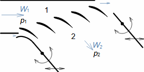
Wind tunnel for measuring blade cascades
2: Wind tunnel for measuring blade cascades
 AERODYNAMICS OF PROFILE CASCADES
4.4
The wind tunnel channel at the outlet consists of moving walls that affect the velocity field at the edges of the cascade and allow the inlet and outlet channels to be pivoted to change the angle of attack. W1, 2 [m·s-1] velocity before and after cascade; p1, 2 [Pa] pressure before and after cascade.

Wind tunnel

Twisted blades

Mach number

Wind tunnels are also used to measure twisted blades, where measurements are also taken along the length of the blades. Wind tunnels are even used in which the aerodynamics of the entire stage can be measured as it rotates. The design of such a test device is given, for example, in [Japikse, 1997, p. 6-23]. The last special group of wind tunnels are supersonic wind tunnels, in which the effects associated with compressibility and supersonic speeds are also investigated, for more details see Mach number and high velocity flow effects [Škorpík, 2023c].

Drag coefficient

Camber of flow

Flow separation

Angle of attack

Aerodynamic characteristics of profile

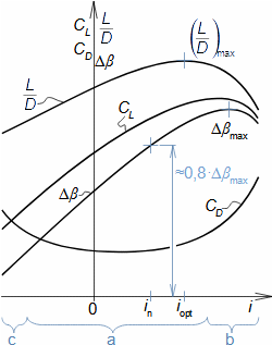
Measured aerodynamic data are usually published in graphical form, see Figure 3. The figure clearly shows that the drag coefficient CD has some minimum and the camber of flow Δβ has some maximum. This is due to the fact that the steady flow through the blade cascade is only stable within a certain interval of angle of attack i. Outside this interval, there is a flow separation from the profile - in the case of a large angle of attack on the suction side of the profiles - or from a certain negative value of the angle of attack on the pressure side of the profiles.

Aerodynamic characteristics of profile cascade
3: Aerodynamic characteristics of profile cascade
Δβ [°] camber of flow; i [°] angle of attack (velocity W1) - index opt indicates optimum angle of attack, when blades reach maximum value of lift in relation to drag value; index n indicates designed nominal angle of attack - it is such angle, which corresponds to camber of flow of approximately 0,8·Δβmax - here blade cascade still has sufficient reserves for changes in operating parameters, without flow separation from profile. a-stable flow region without flow separation; b-region of separation on suction side of blade; c-region of separation on pressure side of blade.
 AERODYNAMICS OF PROFILE CASCADES
4.5

Blade passage

Howell, A. R.

Carter, A. D. S.

Lieblein, S.

Japikse,1997

The blade channels in turbomachines change their shape and size along their length as the profile and pitch of the blades that define these channels change. Especially for twisted blades, there are large changes not only in the geometric but also in the aerodynamic parameters of the flow, so that a large number of measurements are necessary for aerodynamic calculations. Measurement of aerodynamic quantities for a combination of so many variables is time and costly and therefore computational methods have been developed to predict the change in aerodynamic quantities of profiles when some parameters are changed, e.g. Howel's, Carter's, Lieblein's...[Japikse, 1997, p. 5-14]. These methods are particularly useful when trying to reduce the amount of measurements needed for small changes on the profile.

The articel then describes how to determine the individual aerodynamic data from the measurements and also how to use the aerodynamic characteristics of the profile to design the profile cascade of a turbomachine.

Pressure loss of profile cascade

Pressure loss, which is mainly due to internal friction of the working fluid, can be indicated when flowing through any channel. In the case of blade channels, or blade cascade, the pressure loss Lp is defined as the difference by which the pressure behind the cascade p2 must be reduced so that the velocity behind the cascade W2 is the same as the velocity W2is when flowing through the cascade without losses at the outlet pressure p2is, see Equation 4. The condition in front of the cascade is assumed to be the same for both cases.

Pressure loss of profile cascade
4: Pressure loss of profile cascade
Lp [Pa] pressure loss; p2is [Pa] pressure behind cascade at flow without losses; p2 [Pa] pressure behind cascade when same velocity are reached in front of and behind the cascade W1, 2.

Profile loss of profile cascade

Profile losses of the profile cascade are the undesired energy transformations (energy dissipation) in the working fluid that occur during the flow through the profile cascade. Profile losses include, in particular, internal friction losses, flow separation losses from the profile, vortex loss behind trailing edge and shock wave losses at high flow velocities. The sum of these losses gives the total profile loss of the cascade.

 AERODYNAMICS OF PROFILE CASCADES
4.6

Internal friction loss

Laminar flow

Turbulent flow

Internal friction losses in the boundary layer are unavoidable due to internal friction of the working fluid. A characteristic feature of blade channels is their small size and high velocity, so that the boundary layer usually does not fully develop and remains laminar, and there may be turbulence in the jet core if turbulent flow has developed in front of the blade channel. For more on flow transitions in the paper Internal fluid friction and boundary layer development [Škorpík, 2023].

Reynolds number

Airfoil

The Reynolds number, crucial for predicting the boundary layer type, is directly proportional to chord length c. It means, the same velocities, profiles with a small chord length have a small Reynolds number value and vice versa. This is also the reason why aerodynamic coefficients of airfoils are given for large Reynolds numbers - their application is expected as aircraft wing profiles, where the chord length is very large, but for example for turbomachinery blades it is an order of magnitude smaller.

Surface roughness

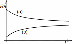
Blade surface roughness affects boundary layer friction but is largely uncontrollable due to contaminants in turbomachine working fluids, which adhere to or damage the surface over time, determining its roughness, see Figure 5.

Change in surface roughness over time
5: Change in surface roughness over time
(a) initially high roughness; (b) initially low roughness. Ra [μm] surface roughness; t [h] operating time. In manufacturing, it is necessary to consider whether it is profitable to produce a very smooth blade if its surface becomes rougher over time.

Flow separation loss

The mechanism of flow separation from the airfoil is already described in the article Aerodynamics of airfoils [Škorpík, 2022]. In addition to energy loss, the consequence of separation can be the collapse of the flow through the blade cascade and blade oscillation.

Diffuser cascade

In diffuser profile cascades, detachment always occurs, see also the article Flow of gases and steam through diffusers [Škorpík, 2023b]. The range of separation can be influenced mainly by the shape of the profile and the angle of attack, respectively by a suitable distribution of pressure changes along the profile, see Problem 1.

 AERODYNAMICS OF PROFILE CASCADES
4.7

Vortex loss behind trailing edge

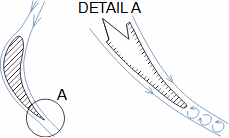
The trailing edges of blades are not sharp mainly for strength reasons, so there is a gap between the flows from the suction and pressure sides of the blades in which small vortexes are formed due to the different velocities of these flows, see Figure 6.

Vortexing behind trailing edge
6: Vortexing behind trailing edge

Shock wave loss

Critical Mach number

The velocity of the flow varies along the profile, so that even if the flow does not reach the speed of sound before the cascade, it can reach or even overcome that speed at a certain attack velocity in the cascade, which we refer to as the critical Mach number of the profile cascade. When the velocity subsequently drops back to subsonic, a shock wave can, under certain conditions, be generated. Details of high velocity flow in profile lattices are given in the chapter Aerodynamics of profile cascades in compressible flow in [Škorpík, 2023c].

Total profile loss

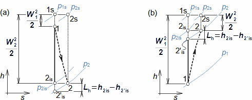
The total profile loss of the cascade can also be expressed as the enthalpy by which the isentropic enthalpy difference behind the cascade must be reduced for the discharge velocity to be the same as in the case of flow without losses, see Figure 7.

Profile loss in blade cascade
7: Profile loss in blade cascade
(a) situation in confuser cascade; (b) situation in diffuser cascade. h [J·kg-1] enthalpy; s [J·kg-1·K-1] entropy; ps [Pa] stagnation pressure; Lh [J·kg-1] profile losses. The index is denotes the change of state in lossless flow.
 AERODYNAMICS OF PROFILE CASCADES
4.8

Loss coefficient of profile cascade

To express the aerodynamic quality of the profile cascade, a quantity called the loss coefficient of profile cascade ξh is used, which is defined as the ratio between the profile loss of the cascade and the stagnation available enthalpy of the working fluid as it flows through the cascade, see Formula 8. The loss coefficient of profile cascade values do not exceed one percent.

Loss coefficient of profile cascade
8: Loss coefficient of profile cascade
(a) confuser blade or uniform pressure blade passage; (b) diffuser blade passage. ξh [1] loss coefficient of profile cascade.

Losses of blade cascades

In blade cascades, not only profile losses occur, but also losses arising from the movement (rotation) of the cascades, the finite length of the blades - losses arising at the blade edges. Collectively, losses on real blade cascades are called losses of blade cascades.

Calculation of forces on blade in linear blade cascade

Force on blade

Ideal flow vs. actual fluid flow

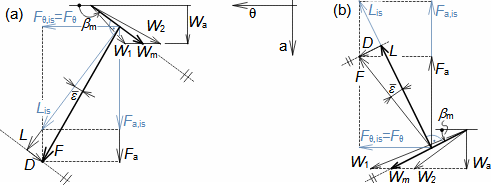
The identification of the individual components of the forces acting on the blade in a linear blade cascade is based on the fact that in actual flow the pressure changes (drops) at the outlet of the cascade so that the velocities and velocity triangles are the same as in lossless flow. This means that, according to theorem of momentum change, the force components acting in the direction-θ (tangential direction) will be the same, since these are a function only of the changes in the velocity components in that direction, and conversely the force components acting in the direction-a (axial direction) will increase. From these assumptions, the individual force components acting on the blade can be plotted in the linear blade cascade, as in Figure 9.

Decomposition of forces acting on a straight blade of certain length in linear blade cascade
9: Decomposition of forces acting on a straight blade of certain length in linear blade cascade
(a) confuser cascade; (b) diffuser cascade. βm [°] angle of mean aerodynamic velocity in cascade; F [N] force acting in given direction; ε‾ [°] glide angle.
 AERODYNAMICS OF PROFILE CASCADES
4.9

Lift coefficient

Drag coefficient

Profile loss

Pressure loss

The equations for calculating the lift and drag coefficient and the profile loss of the profile cascade (Equation 10) can be derived from the previous figure and the pressure loss. These equations can also be used in reverse to calculate the pressure loss based on aerodynamic quantities. Taking Equation 10d for the lift coefficient for the lossless flow case CL,is is derived from the camber of flow requirement and Equation 10b for CL,is is derived from the actual values of the aerodynamic coefficients-the right sides of these equations are equal for a well-designed profile cascades.

Equations for calculation of aerodynamic quantities of profile cascades
10: Equations for calculation of aerodynamic quantities of profile cascades
CL,is [1] lift coefficient for the case of flow without profile losses; σ [1] density of profile cascade. The orientation of the attack and outflow velocity angles β1, β2 is the same as the orientation of the angles βm in Figure 9. The derivation of the equations is given in Appendix 5.

Transferability of linear cascade aerodynamics to aerodynamics of diagonal and radial blade cascades

Transformation equations

Nožička, 1967

Japikse,1997

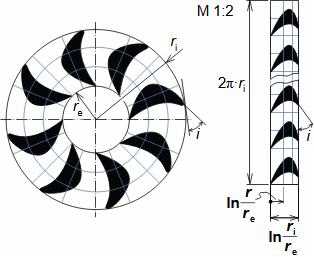
In Problem 2, the application of aerodynamic data obtained from measurements on a linear blade cascade to the axial blade cascade is demonstrated, but these data can also be applied to radial and diagonal blade cascades. In this case, the blade shape of the non-linear cascades must be transformed point by point to the linear cascades. Figure 11 shows an example of transforming the shape of a circular blade cascade to a linear cascade using the transformation equations. A diagonal blade cascade can be transformed in a similar way [Nožička, 1967, p. 84], [Japikse, 1997, p. 7-24]]. Similarly, the pressure and velocity fields measured on a linear blade cascade must be transformed back into circular coordinates by the procedure derived in [Nožička, 1967, p. 84]. These transformation equations are derived under the simplifying assumption of potential flow.

 AERODYNAMICS OF PROFILE CASCADES
4.10
Transformation equation of shape of circular profile cascade to linear
11: Transformation equation of shape of circular profile cascade to linear
r [m] radius of blade cascade.

Transformation of aerodynamic quantities of airfoils into aerodynamic quantities of profile cascades

Airfoil aerodynamics

Aerodynamická interference

Abbott, 1959

When designing profile cascades with low camber profiles on low-cost piece machines where aerodynamic research on the profile cascade cannot be afforded, available airfoils can be used to build the profile cascade. The advantage is that aerodynamic data from measurements of large numbers of airfoils are readily available, see for example [Abbott and Doenhoff, 1959]. The disadvantage is that the aerodynamic coefficients of an airfoil can be expected to have a different value than those of the same airfoil but included in the profile cascade. This is due both to the aerodynamic interference of neighbouring airfoils and to the different definition of the aerodynamic coefficients - in the case of airfoils they are related to the attack velocity, in the case of a profile cascades to the mean aerodynamic velocity in the cascade.

Lift coefficient

Weining coefficient

Lakshminar., 1996

Wang and Kruyt, 2022

The change in the lift coefficient of an airfoil after insertion into a profile cascade can be approximated using Weining coefficient. The Weining coefficient is defined as the ratio of the lift coefficient of a profile cascade composed of flat plates (CL) and the lift coefficient of a isolated flat plate (CLisolated), which is denoted by the letter K, see Formula 12 [Lakshminarayana, 1996, p. 212]. This ratio is derived for flat plates, but is commonly used in profile cascade design to approximate the aerodynamic coefficients of low camber airfoils [Wang and Kruyt, 2022].

 AERODYNAMICS OF PROFILE CASCADES
4.11
Weining coefficient
12: Weining coefficient
CLisolated [1] lift coefficient of isolated plate. The formula has validity up to approximately 1/σ= 0,7, from which value the graph given in [Lakshminarayana, 1996, p. 212] can be used. From a value of 1/σ=2,5, the K factor is close to 1.

Wind turbines

Propellers

Besides the Weinig coefficient, there are other ways to determine the lift coefficient of a profile in a cascade if its parameters are known when measured as an airfoils. These methods are used in the calculation of blade cascades of wind turbines and propellers, more in the article Aerodynamics of wind turbines.

Drag coefficient

If there is no flow separation from the profile, the drag coefficient of the profile in the cascade CD can be expected to be very close to the value that would be measured if the profile were measured as a airfoils, and is therefore not recalculated. Thus, the aerodynamic calculation of a profile cascade designed in this way can be started by using the values of the lift coefficient and the profile drag to calculate the lift coefficient CL,is etc., according to Equation 10 for the lift coefficient CL and the proposed angle of mean aerodynamic velocity βm, see Problem 4.

Base airfoil

In the case of profiles with a camber of a base airfoil (usually profiles with a camber greater than that of airfoils), the calculation of the forces on the blade can be based on the properties of the original base airfoil. The calculation is based on the assumption that the drag coefficient CD of the profile does not change much after cambering, so other force values can be determined based on the calculation of the profile drag in the cascade D as shown in Figure 9.

Problems

Problem 1:
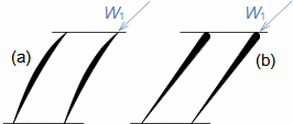
Describe which of the profile cascades (see figure) is likely to be more susceptible to flow separation. The solution to this problem is shown in Appendix 1.
Figure for task
 AERODYNAMICS OF PROFILE CASCADES
4.12
Problem 2:
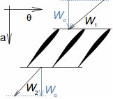
Calculate the pressure loss and loss coefficient of profile cascade of the axial fan rotor. The pressure increase in the rotor blade row is 500 Pa, the relative velocity of air at the inlet to the rotor blade cascade is 46,7 m·s-1, at the outlet 35,4 m·s-1. The density of the working gas is 1,2 kg·m-3. The solution to this problem is shown in Appendix 2.
Axial fan rotor velocity triangle
U [m·s-1] blade speed.
§1   entry:   Δp; W1; W2; ρ §3   calculation:   ξh
§2   calculation:   Lh; Lp    
Procedure for solving the problem 2.
Symbol descriptions are in Appendix 2.
Problem 3:
Calculate the lift and drag coefficient of the blade profile of the Kaplan turbine impeller from Problem 8 in the article Essential equations of turbomachines. Perform the calculation on the mean radius of the blade. The blade number is 6, the length of the blade chord at the mean radius is 1,8 m and the relative profile loss of the blade chord at the radius under investigation is 2,5 %. The solution to this problem is shown in Appendix 3.
Lopatková mříž kaplanovy turbíny
§1   entry:   Z; cξh §4   calculation:   s; σ
§2   read off:   W2; W1; β1; β2; rm §5   calculation:   Lh; CD; CL,is; CL
§3   calculation:   W; W; Wθm; Wm; βm    
Procedure for solving the problem 3.
Symbol descriptions are in Appendix 3.
 AERODYNAMICS OF PROFILE CASCADES
4.13
Problem 4:
Design the attack and outflow velocity and camber of flow parameters and pitch of a diffuser profile cascade assembled from airfoils NACA 65-410 type if the profile cascade is at is designed for the rotor of an axial fan with required pressure rise of 500 Pa and is located at the mean square radius of the blades. The working gas density is 1,2 kg·m-3, the mean square radius of the blades is 1050 mm and the fan rotor speed is 325 min-1. The solution to this problem is shown in Appendix 4.
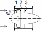
Lopatková mříž axiálního ventilátoru
rm [m] střední poloměr lopatek.
§1   entry   Δp; Wa; ρ; rm; N §9   comparison:   Lh §4 vs. §8
§2   derivation:   rov. pro σ §10   calculation:   γ; CL
§3   calculation:   U; W1; β1 §11   read off:   ν
§4   estimate:   Lh §12   calculation:   c, s, Z
§5   calculation:   W2, β2, σ   rounding:   Z
§6   proposal:   Re   calculation:   s, σ, b
§7   read off:   CLisolated, iisolated=im, CDisolatedCD §13   check:   CL,is
§8   calculation:   Wm, βm, Lh    
Procedure for solving the problem 4.
Symbol descriptions are in Appendix 4.

References

ŠKORPÍK, Jiří, 2022, Aerodynamika profilů, Transformační technologie, Brno, [online], ISSN 1804-8293. https://fluid-dynamics.education/aerodynamika-profilu.html.
ŠKORPÍK, Jiří, 2023, Vnitřní tření tekutiny a vývoj mezní vrstvy, Transformační technologie, Brno, [online], ISSN 1804-8293. https://fluid-dynamics.education/vnitrni-treni-tekutiny-a-vyvoj-mezni-vrstvy.html.
ŠKORPÍK, Jiří, 2023b, Flow of gases and steam through diffusers, Transformační technologie, Brno, [online], ISSN 1804-8293. https://fluid-dynamics.education/flow-of-gases-and-steam-through-diffusers.html.
ŠKORPÍK, Jiří, 2023c, Mach number and high velocity flow effects, Transformační technologie, Brno, [on-line], ISSN 1804-8293. Dostupné z https://fluid-dynamics.education/mach-number-and-high-velocity-flow-effects.html.
ABBOTT, Ira, DOENHOFF, Albert, 1959, Theory of wing sections, including a summary of airfoil data, Dover publications, inc., New York, ISBN-10:0-486-60586-8.
JAPIKSE, David, 1997, Introduction to turbomachinery, Oxford University Press, Oxford, ISBN 0-933283-10-5.
LAKSHMINARAYANA, Budugur, 1996, Fluid Dynamics and Heat Transfer of Turbomachinery, John Wiley & Sons, Toronto, ISBN 0-471-85546-4.
NOŽIČKA, Jiří, 1967, Analogové metody v proudění, Academia, Praha.
WANG, Jie, KRUYT, Niels, P., 2022, "Design for High Efficiency of Low-Pressure Axial Fans With Small Hub-to-Tip Diameter Ratio by the Vortex Distribution Method" J. Fluids Eng., 144(8), https://doi.org/10.1115/1.4053555.
©Jiří Škorpík, LICENCE