5.

INTERNAL LOSSES OF TURBOMACHINES AND THEIR INFLUENCE ON TURBOMACHINE DESIGN

5.3 . . . . . . . . . . . . . .
5.4 . . . . . . . . . . . . . .
5.8 . . . . . . . . . . . . . .
5.8 . . . . . . . . . . . . . .
5.9 . . . . . . . . . . . . . .
5.10 . . . . . . . . . . . . . .
5.11 . . . . . . . . . . . . . .
5.13 . . . . . . . . . . . . . .
5.15 . . . . . . . . . . . . . .
5.16 . . . . . . . . . . . . . .
5.17 . . . . . . . . . . . . . .
5.17 . . . . . . . . . . . . . .
5.19 . . . . . . . . . . . . . .
5.20 . . . . . . . . . . . . . .
5.21 . . . . . . . . . . . . . .
5.22 . . . . . . . . . . . . . .
5.23 - 5.28 . . . . . . . . .
X . . . . . . . . . . . . . . .
5.2
author:
ŠKORPÍK, Jiří – LinkedIn.com/in/jiri-skorpik
issue date:           
September 2022, November 2024 (2nd ed.)
title:
Internal losses of turbomachines and their influence on turbomachine design
proceedings:
provenance:
Brno (Czech Republic)
email:
skorpik.jiri@email.cz

Copyright©Jiří Škorpík, 2022-2024
All rights reserved.

KeywordsINTERNAL LOSSES OF TURBOMACHINES AND THEIR INFLUENCE ON ...
5.3

Essential concepts for description of internal losses in turbomachines

The internal losses Lw as the difference between the ideal work and the actual work of the machine are always caused by some transformation or transfer of energy in the individual parts of the machine with different intensity. Apart from profile losses, other types of internal losses also occur, for example, through leakages, friction between the working fluid and the casing and shaft, etc. The individual types of losses are defined in such a way that they can be added together in the final energy balance of the machine to give the final value of internal losses according to Formula 1. However, many types of losses interact to a greater or lesser degree and this must be taken into account in the final calculation. The calculation of internal losses is done within a single stage (internal stage losses) or the whole machine internal machine losses, etc.

Internal losses
1: Internal losses
Lw [J·kg-1] internal losses in machine part under investigation; Lx [J·kg-1] value of individual loss in machine part under investigation. x-identification of investigated type of loss.

Loss coefficient

The ratio of the individual loss to the ideal work is the loss coefficient (Formula 2a), but depending on the type of machine, the losses and the practices in the field, it can also be defined to the internal work (Formula 2b) or other process.

Loss coefficient
2: Loss coefficient
ξx [1] loss coefficient of individual loss; wid [J·kg-1] ideal work of working fluid; wi [J·kg-1] internal work of working fluid.

Calculation of losses

Ideal process

The calculation of losses is conditioned by the knowledge of the dimensions and parameters of the machine part under investigation and the definition of the ideal process (state). This means that the determination of losses is iterative. For example, by initially designing the machine or part of the machine for the case of no loss flow or with only loss estimates, and only after this design is the actual losses calculated and any changes in dimensions and parameters performed to reduce losses, etc. The calculation is most often based on semi-empirical relationships developed for the machine type, numerical calculations (modelling) or on the designer's ability to use his/her broad knowledge of the behaviour of similar machines/stages to predict the loss for a new yet unresolved case.

KeywordsINTERNAL LOSSES OF TURBOMACHINES AND THEIR INFLUENCE ON ...
5.4

Energy balance

When designing the stage of a turbomachine with losses, the aim is that the sum of losses and Euler work at each radius under investigation should be constant, only in this way can it be achieved that the total energy content at each radius is the same (so-called energy balance condition or specially radial balance).

Aurel Stodola

Carl Pfleiderer

When calculating the losses in an analytical way, the most common method is to rely on the findings of research on turbomachinery carried out by Aurel Stodola (1859-1942; Slovakian-born, professor at the Technical University of Zurich) or Carl Pfleiderer (1881-1960; German engineer, professor at the Technical University of Braunschweig).

Secondary flow loss

In real blade passages, there are losses due to secondary fluid flows respectively fluid flowing outside the required directions. For axial stages, these secondary flows are mainly passage vortices, for radial stages it is the opposite circulation.

Passage vortices

Axial stage

Counter vortices

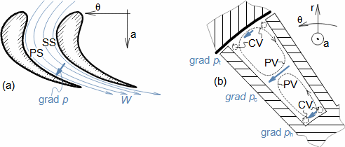
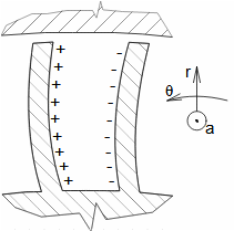
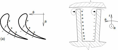
In axial stage blade passages, crossflow occurs as a result of an uneven cross pressure gradient in the blade passage. The pressure gradient has a direction from the suction side of the blade to the pressure side of the adjacent blade, see Figure 3a. The pressure gradient is largest at the core of the flow and smallest at the tips and foot of the blades, where friction against the casing and shaft acts to reduce the flow velocity. The changes in pressure gradients and hence pressure are generated by two opposing passage vortices, see Figure 3b. The passage vortices promote the formation of counter vortices. This phenomenon occurs on both stator and rotor blade passages.

Pressure gradient in blade passage
3: Pressure gradient in blade passage
KeywordsINTERNAL LOSSES OF TURBOMACHINES AND THEIR INFLUENCE ON ...
5.5
(a) formation of pressure gradient in blade passage; (b) formation of transverse flow due to different pressures, resp. their gradients between core c and foot h and tip t. SS-suction side of blade; PS-pressure side of blade; PV-passage vortices; CV-counter vortices. p [Pa] pressure; W [m·s-1] relative velocity of working fluid. r-radial direction; θ-tangential direction; a-axial direction.

Angle of attack

Mach number

Dixon and Hall, 2010

The value of the secondary flow loss increases, for example, with increasing angle of attack and decreasing Mach number. A prediction of the changes in velocity angles due to secondary flow for twisted blades is made, for example, in [Dixon and Hall, 2010, p. 212].

Bowed-twisted blade

Sloping blade

Japikse, 1997

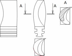
To reduce the secondary flow loss of axial stages, sloping the blades away from the radial axis is done, but more effective is blowed them (Figure 4) [Japikse, 1997, p. 6-13].

Bowed-twisted blade
4: Bowed-twisted blade (3D stacks)

Bowed-twisted blade

Axial stage

Euler work

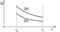
The shape of the Bowed-twisted blade of the axial stage is not designed under the condition of constant circulation of the tangential velocity component (the condition of the irrotational vortex), but on the contrary under the condition of its change according to some exponential function. For example, according to the function defined by Equation 5, see Figure 6. This equation is advantageous in that the Euler work along the length of the blades is constant as in the case of potential flow (the irrotational vortex equation is a special case of this equation).

Axial stage equations with constant Euler work and exponential velocity circulation
5: Axial stage equations with constant Euler work and exponential velocity circulation
V [m·s-1] absolute velocity; r [m] radius; wE [J·kg-1] Euler work on investigated radius; ω [rad·s-1] angular velocity of rotor rotation; a, n [SI] proposed constants; b [SI] constant (can be calculated from proposed Euler work on reference radius).
KeywordsINTERNAL LOSSES OF TURBOMACHINES AND THEIR INFLUENCE ON ...
5.6
Tangential velocity component profile along length of blades
6: Tangential velocity component profile along length of blades
(a) r·Vθ=const.; (b) Vθ profile according to Equation 5 (n<-1).

Angle of relative velocity

The exponential profile of the velocity circulation causes the relative velocity angle to vary so that at the tip of the blade it can be very close to the angle at the foot of the blade, although at the center of the blade it is very different, see Figure 7.

Bowed-twisted blade
7: Bowed-twisted blade designed according to Equation 5

Opposite circulation

Coriolis acceleration

The opposite circulation (or relative eddy) is caused by the action of the Coriolis acceleration on the flowing working fluid in the radial direction, therefore this circulation has a more significant effect the larger the radial component of the flow. It significantly affects the flow in radial stages, see Figure 8a. This phenomenon is analogous to cyclones forming in the Earth's atmosphere.

Flow separation

Radial stage

Opposite circulation increases the susceptibility to flow separation from the blades of centrifugal stages of working machines. For forward curved blades this susceptibility is greater because the centrifugal acceleration is directed away from the suction side of the blades. For backward curved blades, the susceptibility to flow separation is less because the centrifugal acceleration is directed towards the suction side of the blades, thus partially stabilizing the boundary layer, see Figure 8(b, c). For these reasons, the density of a blade cascades with radial forward curved blades is higher than that of a cascades with backward curved blades, although this implies higher profile losses.

KeywordsINTERNAL LOSSES OF TURBOMACHINES AND THEIR INFLUENCE ON ...
5.7
Opposite circulation in blade passage of radial stage
8: Opposite circulation in blade passage of radial stage
(a) direction of opposite circulation; (b) centripetal flow; (c) centrifugal flow. Ω [rad·s-1] angular velocity of opposite circulation; ar [m·s-2] centrifugal acceleration; ac [m·s-2] Coriolis acceleration.

Radial velocity component

Tangential velocity component

Slip

Opposite circulation causes uneven radial velocity component in the blade passage — accelerating one side, decelerating the other — and the change in the tangential component of the outlet velocity, which is called slip (Figure 9(a, b)). Opposite circulation in effect reduces the value of the Euler work due to the unfavourable change in the tangential component of the velocity W and hence V at the rotor outlet.

Change in radial and tangential velocity components due to effect of opposite circulation
9: Change in radial and tangential velocity components due to effect of opposite circulation
ΔWθ [m·s-1] deviation of tangential component of relative velocity at rotor outlet caused by opposite circulation.

Slip coefficient

Dixon and Hall, 2010

A quantity called the slip coefficient is used to predict the effect of the opposite circulation on the Euler work. The slip is defined separately for the turbine stages (Figure 10) and for the working machine stages (Figure 11).

Definition of slip coefficient of radial cetripetal turbine
10: Definition of slip coefficient of radial cetripetal turbine
(a) effect of opposite circulation on flow; (b) in case of centripetal turbines it is possible to compensate slip by changing angle of absolute velocity in front of rotor, thus changing angle of relative velocity; (c) general formula for slip coefficient; (d) special formula for slip coefficient at β1∞=90° (other cases, for example, in [Dixon and Hall, 2010, p. 279]). μ [1] slip coefficient for centripetal turbines; β [°] relative velocity angle. V-vortices that arise during flow separation from blades. The index denotes the parameters of the velocity triangle for the case of an infinite number of blades (the case where no opposite circulation arises).
KeywordsINTERNAL LOSSES OF TURBOMACHINES AND THEIR INFLUENCE ON ...
5.8
Slip coefficient of centrifugal stage of working machine
11: Slip coefficient of centrifugal stage of working machine
μ [1] slip coefficient for centrifugal stages of working machines (formulas for its calculation are given, for example, in [Dixon and Hall, 2010, p. 239]).

Tip clearance losses

Counter vortices

Tip clearance losses is the negative effect of the overflow of the working fluid at the blade tips from the pressure side to the suction side, which also causes counter vortices, see Figure 12.

 Overflow of working fluid over edges of blades
12: Overflow of working fluid over edges of blades

Shroud

Shroud disc

Tip clearance losses for the case of short blades can be of the same order of value as for profile losses, but their relative value decreases significantly with blade length. Tip clearance losses can be reduced by using shrouds to prevent overflow over the blade edge. For radial stages, a shroud disc can be used to prevent tip clearance loss, see Figure 20b.

Tip leakage losses

Shroud

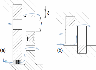
There must be a radial gap δ between the rotor blades and the casing, respectively between the stator blades and the shaft, even if shrouds are used, see Figure 13. The working fluid that leaks through this gap does not do any work and therefore represents a loss. The value of this loss depends on the design of the stage and the shroud.

KeywordsINTERNAL LOSSES OF TURBOMACHINES AND THEIR INFLUENCE ON ...
5.9
Tip leakage losses
13: Tip leakage losses
(a) leakage in case of impulse stage with disc type rotor and blades with shrouds; (b) loss of internal leakage in case of stage without shrouds. Lm [kg·s-1] mass flow through stage leaks; δ [m] radial gap length; l [m] blade length.

Disc type rotor

Japikse, 1997

Zekui, 2025

Flow through leaks can disrupt the main flow because it has higher energy. Therefore, in the case of disc type rotors, the leakage of the previous blade cascade is sucked out through a hole in the disc outside the blade passages (Figure 13a). The leakage of blades without shrouds also affects the tip clearance losses, see Problem 1. Formulas for approximate determination of the tip leakage losses are given in [Japikse, 1997, pp. 6-35], [Zekui et. al., 2025] (in Czech [Kadrnožka, 2004, p. 95, 200]).

Misárek, 1963

The loss coefficient of tip leakage loss decreases with the length of the blades, respectively with the ratio of the length of the blades l and the radial gap δ. In addition, for working machine stages, leakage can be positive in some operating conditions because it stabilizes the stage flow. The dependence of the blade length on the efficiency of the compressor stage is given, for example, in [Misárek, 1963, p. 73].

Loss of uneven velocity distribution in front of cascade

Boundary layer

Velocity triangle

There is a uneven velocity distribution at the outlet of the blade cascade, which is caused by friction in the boundary layer of the flow at the blade surfaces on both the suction and pressure sides. This non-uniform velocity contour of the working fluid causes the attack angle and velocity, respectively the velocity triangle, to change alternately as the rotor blade cascade moves through such the velocity field, see Figure 14.

KeywordsINTERNAL LOSSES OF TURBOMACHINES AND THEIR INFLUENCE ON ...
5.10
Uneven velocity distribution at stator blade cascade outlet and its effect on velocity triangle
14: Uneven velocity distribution at stator blade cascade outlet and its effect on velocity triangle
S, R-stator or rotor blade cascade; VC-velocity contour in gap between cascades of blades. U [m·s-1] blade speed. The velocity triangle in the core region of the flow is drawn in dashed lines, the velocity triangles in the trailing edge region, where the influence of the boundary layer is fully manifested, are drawn in solid lines.

Flow separation

Blade oscillation

Kaplan turbine

The uneven velocity distribution also contributes to increase the sensitivity of the diffuser blade passages to flow separation from the blades and excitation of oscillations at a frequency corresponding to a multiple of blade number and rotational speed. The excitation of oscillations from the uneven velocity distribution can be influenced by changing the number of rotor blades, compared to the stator, or by increasing the gap between the blade cascades, but this leads to increased pressure loss between the cascades of blades and an increase in machine size. For example, the gap between the stator and rotor cascades is very pronounced in Kaplan turbines.

Loss from incorrect angle of attack

Flow separation

Kadrnožka, 2004

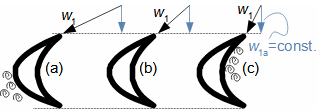
Loss from incorrect angle of attack occurs when the working fluid flow direction into the blade passage is incorrect. The angle of attack is then too large or too small compared to the design condition, which can lead to flow separation from the blade Figure 15. This loss occurs when the leading edge of the blades does not respect the changes in the blade speed and therefore the angle of attack - it is particularly relevant for straight blades of axial stages and inducers of radial stage. It can also occur in twisted blades when volume flow or rotational speed changes. Formulas for its determination are given, for example, in [Kadrnožka, 2004, p. 100].

Changing angle of attack of straight blade
15: Changing angle of attack of straight blade
(a) flow at foot of blades; (b) flow at mean diameter (in core of blade passage); (c) flow at tip of blade. i [°] angle of attack.
KeywordsINTERNAL LOSSES OF TURBOMACHINES AND THEIR INFLUENCE ON ...
5.11

Turnable blades

Rotational speed

Inlet guide vanes

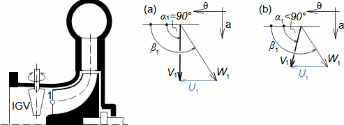
The optimum angle of attack when changing the flow through the stage can be kept by changing the rotational speed. If it is not possible to change the rotational speed, then the angle of attack can be kept within the optimum limits by turnable blades. For single stage axial and radial work machines, inlet guide vanes can also be used, see Figure 16. When the flow rate is changed, the inlet guide vanes are rotated so that the inlet angle of the relative velocity to the rotor cascade is changed as little as possible, thus achieving the least decrease in efficiency due to the change in angle of attack.

Regulation of angle of attack into rotor of radial compressor stage by using inlet guide vanes
16: Regulation of angle of attack into rotor of radial compressor stage by using inlet guide vanes
(a) velocity triangle at leading edge of inducer in case of nominal flow; (b) deflection of absolute velocity from axial direction by inlet guide vanes so that inlet angle β1 is kept even at reduced flow. IGV-inlet guide vanes. α [°] absolute velocity angle; β [°] relative velocity angle.

Loss through backflow

This type of loss is related to a reduction in the mass flow rate of the stage compared to the nominal state. In the case of reduced flow, significant flow separation from the meridional surfaces of the blade passages (at the foot of the blades) and backflow can occur, as shown in Figure 17.

17: Backflow of long twisted blade when flow through turbine stage is reduced
KeywordsINTERNAL LOSSES OF TURBOMACHINES AND THEIR INFLUENCE ON ...
5.12

Kaplan turbine

Francis turbine

Hesari et al., 2024

Backflow in the blade passage can be avoided by rotating the blades or by changing the rotational speed. For example, in Kaplan turbines, backflow can be avoided very well by rotating the rotor blades, but in Francis turbines outside the optimal operating condition, there are already backflow problems, see more in [Hesari et al., 2024].

Specific mass flow

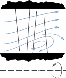
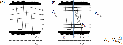
In addition, the formation of backflow in thermal machines is supported by an increase in the density of the working gas at the blade tips due to centrifugal forces. This means that, for a purely axial stage designed for a constant value of the axial velocity component Va(r)=const. one can expect a streamline shape as in Figure 18a and most of the working gas will flow closer to the outer radius of the blades even at nominal flow. Uniform flow through the axial stage of the thermal machine (and thus reduce susceptibility to backflow loss) can be ensured by imposing a constant specific mass flow condition through the stage. Such a stage is designed to have the same specific mass flow (mass flow per mm2 of flow area) in the axial direction at each flow area, see Figure 18b - in the case of incompressible fluids this condition is always satisfied.

Principle of stage design with constant specific mass flow
18: Principle of stage design with constant specific mass flow
(a) streamline deflection in stage designed for Va(r)=const.; (b) design principle of stage with constant specific mass flow. v [m3·kg-1] specific volume.

Axisymmetric potential flow

Conical stage

Purely axial stages through which compressible fluid flows, designed for constant specific mass flow, do not satisfy the conditions for axisymmetric potential flow - specifically, the condition that the radial component of the velocity in the axial direction must change with the change in the axial component of the velocity in the radial direction is not satisfied. However, axial stages designed in this way have greater efficiencies outside the optimum condition than stages designed for a constant value of the axial velocity component - especially at reduced flow rates, because the flow through the stage is more uniformly distributed.

KeywordsINTERNAL LOSSES OF TURBOMACHINES AND THEIR INFLUENCE ON ...
5.13

Losses due to change of meridional velocity

Outlet velocity

Flow area

It is an effort to make the outlet velocity of the turbomachine the same as the inlet velocity. If the outlet velocity is higher, it means the energy of the working fluid was not transformed into internal work, but remained as kinetic energy, which represents a loss. Of course, there are cases where an increase in outlet velocity is desirable (propellers, jet engines, etc.). Changing the meridian velocity can generate other types of losses as well. For example, in heat turbines, the specific volume increases during expansion and not only the outlet velocity but also the profile losses increase for the same flow areas. Similarly, compression in turbocompressors results in a decrease in velocity for the same flow area. That is, frictional losses may decrease, but as velocity decreases, blade camber must be increased (to maintain the same Euler work of stage, or tangential velocity component), which can lead to flow separation from the blades.

Normal stage

Twisted blade

For heat turbines and turbocompressors, it is therefore necessary to gradually change the flow areas so that the inlet and outlet velocities of the stage remain approximately the same. Stages with this condition are also called normal stages. While for radial stages the changes in the inlet and outlet flow areas do not have a significant effect on the stage design procedure, for axial stages the design intervention is much more significant because the radial component of the velocity must also be considered as the blade lengths change - hence the term conical stage, see Figure 19.

Examples of cone stage performances
19: Examples of cone stage performances
ε [°] angle between axial direction and direction along conical surface. Further examples of conical stages are shown in the article Thermodynamics of heat turbines.
KeywordsINTERNAL LOSSES OF TURBOMACHINES AND THEIR INFLUENCE ON ...
5.14

Conical stage

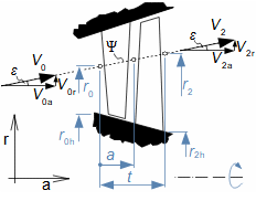
Conical stages are stages with varying blade lengths within a single stage in which the design flow surfaces are conical, see Figure 20. They are used in compressible flow to compensate for the change in density so that the axial velocity component at the outlet of the stage is the same as at its inlet.

Conical stage with twisted blades
20: Conical stage with twisted blades
Ψ-examined streamline; t [m] length of stage. The figure shows example of flow over purely conical surfaces in turbine stage. The formula is written in the form for the turbine stages, and the same formula applies for the working machine stages, except that it is sufficient to replace index 0 by 1 and index 1 by 3. The derivation of the equation, assuming V=V=0, is shown in Appendix 3.

Specific mass flow

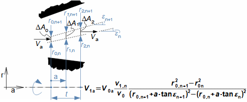
The last formula gives an explicit relationship between the axial and radial components of the velocity, because the angle of the conical surface ε can be calculated from the length of the stage t. The conical stage takes into account the change in density and is designed under the condition of constant specific flow. This means that the axial component of velocity is variable in the radial direction (Formula 21), and since the radial component also varies in the axial direction, such a design is close to the assumptions of potential flow.

Formula for axial velocity component of conical stage with constant specific mass flow
21: Formula for axial velocity component of conical stage with constant specific mass flow
A [m2] flow area; n-number of flow area. The axial velocity is calculated just in front of the leading edge of the blade and behind the trailing edge of the blade. A change in the radius between the blade cascades causes the outlet triangle of the previous cascade to be different from that of the next cascade, and not only the axial but also the tangential velocity component must be recalculated. The formula is written in the form for the turbine stages, and the same formula applies for the working machine stages, except that it is sufficient to replace index 0 by 1 and index 1 by 3. The derivation of the formula is shown in Appendix 4.
KeywordsINTERNAL LOSSES OF TURBOMACHINES AND THEIR INFLUENCE ON ...
5.15

Reaction

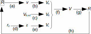
Reaction R for each radius must be calculated iteratively. First, an estimate of the reaction for the radius under investigation is made and from this the working gas parameters are determined, from which the velocities and reaction are then calculated and the value of reaction is compared with the estimate, see Figure 22.

 Iterative calculation of reaction of axial stage
22: Iterative calculation of reaction of axial stage
R [1] reaction. (a) estimate reaction R and from h-s diagram or by calculation determine specific volume at outlet of first blade cascade; (b) calculate axial velocity component; (c) calculate tangential velocity component from constant velocity circulation formula and given triangle on reference radius; (d) calculation of outlet radius of stage according to Formula 20 and angle ε; (e) calculation of radial component of velocity; (f) calculation of absolute velocity; (g) calculation of reaction from velocities; (h) comparison with original estimate of reaction, if the accuracy of the estimate was not sufficient, then calculation is repeated with new estimate. The index ref denotes the entered parameters at the reference radius.

Kadrnožka, 2004

Pfleiderer and Petermann, 2005

The above procedure for designing a conical stage is only one of many possible variations; for example, in [Kadrnožka, 2004], [Pfleiderer and Petermann, 2005] the slope of the conical surfaces is prescribed and then the inlet and outlet velocities of the stage are iteratively calculated at individual radii.

Rotor friction loss

Rotor

Euler work

Friction

Disc type rotor

Radial stage

Shroud

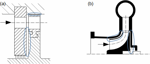
Rotor friction loss is equivalent to the portion of Euler work that must be expended to overcome the frictional resistance of the working fluid against the rotation of the rotor - so the mean value of Euler work must be greater than the internal work of the stage. Significant rotor friction losses arise, for example, in disc type rotor (Figure 23a) where there is a relatively large disc area in contact with the working fluid enclosed between the disc and the stator. It is also significant in radial stages (Figure 23b). Rotor friction loss also occurs at the bounding surfaces between the rotor and stator (shroud), but this loss is relatively small.

KeywordsINTERNAL LOSSES OF TURBOMACHINES AND THEIR INFLUENCE ON ...
5.16
Occurrence of rotor friction loss between discs
23: Occurrence of rotor friction loss between discs
(a) main friction surfaces between discs of axial stage; (b) main friction surfaces of radial stages.

Heat transfer

The heat generated by friction on the friction surfaces is transferred to the working fluid and the machine mass, see Formula 24.

 Heat flow distribution from rotor friction loss
24: Heat flow distribution from rotor friction loss
wr [J·kg-1] rotor friction loss; qr [J·kg-1] heat from rotor friction loss; δ [1] heat flow distribution coefficient from rotor friction loss; δ·wr [J·kg-1] part of frictional heat transferred to machine walls (heat transferred to surroundings); (1-δ)wr [J·kg-1] part of frictional heat transferred to working fluid.

Pfleiderer and Petermann, 2005

Kousal, 1980

Semiempirical formulas are used to calculate rotor friction losses, e.g., [Pfleiderer and Petermann, 2005, p. 323] or [Kousal, 1980, p. 249] for rotors without a shroud disc include tip clearance losses. These formulas are a function of rotor dimensions and shape and rotational speed.

Losses in inducer of radial stage

Inducer

For purely radial stages, vortices may form near the leading edges of the inducer, see Figures 25(a, b). To reduce the effect of these vortices, stages are designed with a gradual reduction in radial blade width, Figure 25c.

Vortices are also formed at the tips of the radial stage blades at the point of transition from axial to radial direction. These vortices are formed by displacement of a portion of the working fluid at the blade tips by the higher pressure radial flow, see Figure 25d.

Flow reduction for pure radial stage
25: Flow reduction for pure radial stage
KeywordsINTERNAL LOSSES OF TURBOMACHINES AND THEIR INFLUENCE ON ...
5.17

Misárek, 1963

Extensive information from measurements of the effect of different types of losses on the efficiency of the radial compressor stage is shown in [Misárek, 1963].

Loss due to partial admission

Flow separation

Friction

Kadrnožka, 2004

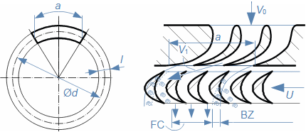
Loss due to partial admission occurs in cases where fluid flows into the stage on only part of the circumference of the rotor blade cascade, see Figure 26. The loss is realized in the marginal zones (swirling of the fluid due to the flow separation from the blades) and by friction of the blades against the stationary working fluid outside the working area. Details on the mechanism of loss due to partial admission and its approximate calculation are shown in [Kadrnožka, 2004, p. 196].

26: Partial admission rotor blade cascade
a [m] length of stator blade cascade (nozzle group); l [m] length of blades; FC-flow core; BZ-border zone.

Laval turbine

Nozzle governing

Combustion turbine

Loss due to partial admission occurs in single-stage turbines, e.g. Laval turbines (where the stator cascade of blades does not cover the entire circumference) or in nozzle governing steam turbines and also in combustion turbines with tube combustion chambers.

Example of procedure to design stage with losses

Model

When deciding on the design procedure for a turbomachine stage, the requirements for its power parameters, price, cost of operation, method of operation and whether it is a machine for series production or piece production are taken into account. For this reason, a universal procedure for calculating turbomachine losses cannot be described. The design of the flow parts of turbomachines can generally be said to be designed according to analytical calculation models and their parameters can be optimised and refined using computer calculation models.

KeywordsINTERNAL LOSSES OF TURBOMACHINES AND THEIR INFLUENCE ON ...
5.18

2D calculation

Energy balance

Euler work

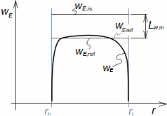
In the analytical design, we perform either a 1D or 2D calculation. In the case of 2D calculation, the energy balance condition must be respected. This means that the basis is the prediction of the Euler work at each investigated radius of the stage such that the sum of the losses and the Euler work must be the same at each radius. From the previous sections on losses, it is clear that it is almost impossible to design a turbomachine stage that has the same Euler work respectively losses at all radii. However, for the first iteration, the distribution of Euler work is estimated according to the equation for the irrotational vortex, or Equation 5 for the bowed blades, which were derived for a constant value of Euler work, see Figure 27. Only in later iterations are the losses and work for individual radii calculated more accurately as needed, based on the stage parameters derived from the previous iteration.

Comparison of Euler work of axial stage in isentropic and real flow with losses
27: Comparison of Euler work of axial stage in isentropic and real flow with losses
wE,is [J·kg-1] Euler work during lossless flow; wE,ref [J·kg-1] proposed linear (constant) Euler work partially respecting mean stage losses; Lw,m [J·kg-1] mean profile stage losses. The figure is drawn for axial stage turbine, the Euler work profile of the working stage is shown in the article Thermodynamics of turbocompressors.

Reaction

The first iteration of the 2D calculation of the stage starts with estimating the mean value of the internal losses of the stage and proposing the basic parameters on a reference radius (if not part of the specification), which is usually the radius at the foot or the mean square radius. The parameters at the other radii are calculated from the parameters at the reference radius over the value of the reaction. In the case of hydraulic machines, respectively for incompressible fluid, the axial stage reaction formulas can be derived for each radius, see Formula 28. In the case of compressible fluid, the iterative loop of Figure 22 must be used, see Problem 2.

KeywordsINTERNAL LOSSES OF TURBOMACHINES AND THEIR INFLUENCE ON ...
5.19
Reaction of axial stage with constant Euler work and incompressible fluid
28: Reaction of axial stage with constant Euler work and incompressible fluid
(a) reaction for case of tangential velocity component proposal according to Formula 5; (b) reaction for case of tangential velocity component proposal according to equation for irrotational vortex (n=-1). The index ref denotes the quantity at the reference radius of the blade. The derivation is shown in Appendix 5.

Losses in turbomachine branches

The branches must keep the fluid pressure uniform around the entire circumference of the inlet part of the first stage and the outlet part of the last stage of the machine. In the inlet branches, the working fluid is usually slightly accelerated towards the first stage. In the outlet branches, the working fluid is usually slightly decelerated towards the last stage. In both cases, the change in velocity compensates for the pressure loss. The loss in the branch is usually related to the kinetic energy of the fluid in front of the branch, see Formula 29.

Loss coefficient and specific loss in branch
29: Loss coefficient and specific loss in branch
Lh,B [J·kg-1] branche loss; Vi [m·s-1] mean velocity in branche inlet section; Lp [Pa] branche pressure loss; ρ [kg·m-3] density; ξB [1] loss coefficient of branche.

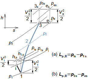
h-s chart of branche

Figure 30 shows the h-s chart of the thermodynamic changes occurring in the branches of a working machine. The pressure in the inlet branche gradually decreases as the flow area reduces (suction takes place here). Approximately throttling occurs in the outlet branche to compensate for the branche pressure loss (total pressure decreases), or there is a slight compression to stabilize the boundary layer. Especially for fans, there is a direct diffuser behind the outlet branch, in which part of the kinetic energy of the gas is transformed into pressure energy.

KeywordsINTERNAL LOSSES OF TURBOMACHINES AND THEIR INFLUENCE ON ...
5.20
h-s chart of single-stage working machine with inlet and outlet branche
30: h-s chart of single stage working machine with inlet and outlet branche
(a) pressure loss in inlet branche (change i-1); (b) pressure loss in outlet branche (change 3-e). Index i denotes the working gas state at the inlet, index e denotes the state at the outlet, index 1 denotes the working gas state in front of the rotor, index 2 denotes the state behind the rotor, index 3 denotes the state at the outlet of the stage (rotor+diffuser), index s denotes the stagnation state.

Internal efficiency

Kadrnožka, 2003

Macek, 1988

Data for estimation of branche losses are shown in [Kadrnožka, 2003, p. 143], [Macek, 1988, p. 58]. The share of branche losses in the internal losses of the machine decreases with the number of stages, respectively for single stage machines they have a significant effect on the internal efficiency.

Losses through external leakage

Extraction

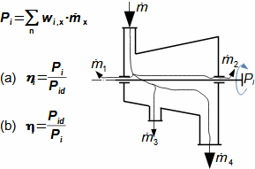
The working fluid can flow through the machine through many paths including leaks and required extractions, then the internal power of the machine is the sum of the internal power on each path, see Figure 31.

Internal power of turbomachine including external leakage
31: Internal power of turbomachine including external leakage
wi [J·kg-1] internal work; Pi [W] internal power of machine; m [kg·s-1] mass flow through individual paths (possibly also extractions). x-path number.
KeywordsINTERNAL LOSSES OF TURBOMACHINES AND THEIR INFLUENCE ON ...
5.21

Problems

Problem 1:
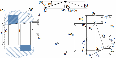
Find the internal losses and internal power of the axial stage of a steam turbine with straight blades. The calculated Euler work efficiency at the mean radius of the stage is 0,8405. The other parameters of the stage are as follows: rm=325 mm; δ=0,5 mm; l=25,6425 mm; α1=20°; U1=102,1018 m·s-1; V1=147,4688 m·s-1; V2=62 m·s-1 (the stage is normal i.e. designed for velocity equality V0=V2); Lh=3,3970 kJ·kg-1 (profile losses); Δhis=21,3 kJ·kg-1, m=12 kg·s-1. The solution of the problem using the models used at PBS is shown in Appendix 1.
Expanze ve stupni parní turbíny
(a) meridional section of stage; (b) velocity triangle on mean radius; (c) h-s diagram of stage. ηE [1] Euler work efficiency; l [mm] blade length; α [°] absolute velocity angle; W [m·s-1] relative velocity; h [J·kg-1] enthalpy; s [J·kg-1·K-1] entropy; Lh [kJ·kg-1] profile losses at mean radius; Lw [kJ·kg-1] internal losses; Δhis [kJ·kg-1] isentropic change of enthalpy; m [kg·s-1] mass flow. The index m denotes the mean radius of the blades.
§1   entry:   ηE; rm; δ; l1; α1; U; V1; V2; Lh; Δhis; m §3   calculation:   ξh; ξCTL; ξAL; Lw; wi; Pi
§2   calculation:   wis    
The symbol descriptions are shown in Appendix 1.
Problem 2:
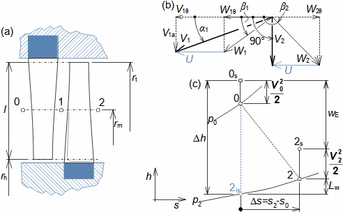
Carry out the basic design of the last stage of a steam turbine with twisted blades with constant Euler work along the length of the blades. Carry out the design for a flow with losses, assuming that the value of the profile loss is constant along the length. The given parameters are: p0=13 kPa; h0=2488 kJ·kg-1; ξw=0,1 (relative to the value of Δh); V0=70 m·s-1; p2=3,42 kPa; N=50 s-1; m=52 kg·s-1. Carry out the calculation at least for the foot, the tip of the blade and the mean radius of the blade. The solution to the problem is shown in Appendix 2.
KeywordsINTERNAL LOSSES OF TURBOMACHINES AND THEIR INFLUENCE ON ...
5.22
Obrázek k úloze 1035
(a) meridional section of stage; (b) design of shape of velocity triangle; (c) h-s diagram on individual radii with only profile losses.
1.   entry:   ξw; p0; h0; V0; p2; N; m; Rh 5.   calculation:   rh
2.   calculation:   states 0; 2; wE; ηE ... 6.   calculation:   R for rt a rm
3.   calculation:   states 1 for rh 7.   calculation:   velocity triangle parameters for rt a rm
4.   calculation:   velocity triangle parameters for rh    
The symbol descriptions are shown in Appendix 2.

References

DIXON, S., HALL, C., 2010, Fluid Mechanics and Thermodynamics of Turbomachinery, Elsevier, Oxford, ISBN 978-1-85617-793-1.
HESARI, Rezavand, MUNOZ, Anthony, COULAUD, Maxime, HOUDE, Sébastien, MACIEL, Yvan, 2024, The Measured Flow at the Inlet of a Francis Turbine Runner Operating in Speed No-load Condition, Journal of Fluids Engineering, ASME, New York, ISSN 0098-2202, doi: https://doi.org/10.1115/1.4065384.
JAPIKSE, David, 1997, Introduction to turbomachinery, Oxford University Press, Oxford, ISBN 0-933283-10-5.
KADRNOŽKA, Jaroslav, 2003, Lopatkové stroje, Akademické nakladatelství CERM, s.r.o, Brno, ISBN 80-7204-297-1.
KADRNOŽKA, Jaroslav, 2004, Tepelné turbíny a turbokompresory, Akademické nakladatelství CERM, s.r.o., Brno, ISBN 80-7204-346-3.
KOUSAL, Milan, 1980, Combustion turbine, Nakladatelství technické literatury n. p., Praha.
KRBEK, Jaroslav, 1990, Tepelné turbíny a turbokompresory, Vysoké učení technické v Brně, Brno, ISBN 80-214-0236-9.
MACEK, Jan, KLIMENT Vladimír, 1988, Spalovací turbiny, turbodmychadla a ventilátory: (přeplňování spalovacích motorů), Nakladatelství ČVUT, Praha, ISBN 80-01-03529-8.
MISÁREK, Dušan, 1963, Turbokompresory, Statní nakladatelství technické literatury, n.p, Praha.
PFLEIDERER, Carl, PETERMANN, Hartwig, 2005, Strömungsmaschinen, Springer Verlag Berlin, Heidelberg, New York, ISBN 3-540-22173-5.
ZEKUI, Shu, SHUIGUANG, Tong, ZHEMING, Tong, JINFU, Li, 2025, A Rapid Theoretical Approach for Estimating the Energy Losses Induced by Tip Clearance Jets in Centrifugal Pumps, Journal of Fluids Engineering, ASME, New York, ISSN 0098-2202, doi: https://doi.org/10.1115/1.4068461.

Additional media content

©Jiří Škorpík, LICENCE